sewing presser feet guide

Sewing presser feet are essential attachments that enhance fabric control and precision․ They come in various types‚ each designed for specific tasks‚ from zippers to quilting․ Interchangeable and versatile‚ they unlock your machine’s full potential‚ ensuring professional results for every project․

1․1 What Are Sewing Presser Feet?

A sewing presser foot is an essential attachment that holds fabric in place and guides it smoothly under the needle during sewing․ Designed to fit onto the sewing machine’s shank‚ presser feet come in various styles to suit different sewing tasks‚ from basic straight stitching to intricate embroidery or quilting․ They are typically made of metal or clear plastic and may be universal or specific to certain machine brands․ Presser feet ensure even fabric feeding‚ prevent dragging‚ and help achieve precise results․ Whether you’re working with delicate fabrics‚ heavy materials‚ or specialized techniques like zippers or buttonholes‚ the right presser foot can make a significant difference in the quality of your stitches․ By enhancing control and versatility‚ presser feet are indispensable tools for sewists of all skill levels‚ helping to unlock the full potential of their sewing machines․

1․2 Importance of Using the Right Presser Foot

Using the right presser foot is crucial for achieving professional results in sewing․ It ensures even fabric feeding‚ prevents dragging‚ and avoids missed stitches‚ especially on challenging materials like leather or vinyl․ The correct foot enhances control‚ allowing precise stitching and smooth navigation‚ even on intricate designs or heavy fabrics․ This leads to cleaner seams‚ reduced fabric waste‚ and faster completion of projects․ Additionally‚ the right presser foot minimizes the risk of damage to delicate fabrics and ensures consistent results․ By matching the foot to the task‚ sewists can unlock their machine’s full potential‚ tackle a wider range of projects‚ and achieve high-quality finishes effortlessly․ Whether quilting‚ embroidering‚ or installing zippers‚ the right presser foot is essential for efficiency and versatility in sewing․

Types of Sewing Presser Feet

Sewing presser feet come in various styles‚ each designed for specific tasks․ From standard and zipper feet to walking and non-stick options‚ they cater to diverse sewing needs‚ enhancing accuracy and versatility for every project․

2․1 Standard Presser Foot

The standard presser foot‚ often called the zigzag or straight stitch foot‚ is the default attachment that comes with most sewing machines․ It features a wide opening to accommodate the needle’s movement‚ making it ideal for straight stitches and basic sewing tasks․ This foot is versatile and works well for seaming‚ topstitching‚ and edge stitching․ It is particularly useful for fabrics that require a straight stitch‚ such as cotton and linen‚ and is a great starting point for beginners․ The standard presser foot is also compatible with zigzag stitches‚ making it suitable for general-purpose sewing․ Its simplicity and reliability make it an essential tool for any sewing project․ Whether you’re working on garments‚ home decor‚ or repairs‚ the standard presser foot is a go-to choice for consistent results․

2․2 Zipper Presser Foot

The zipper presser foot is a narrow‚ specialized attachment designed to make sewing zippers quick and precise․ Its slim design allows you to sew close to the zipper teeth‚ ensuring a professional finish․ The foot typically features notches on both sides‚ enabling you to align the needle to the left or right of the zipper․ This makes it easy to sew zippers for bags‚ garments‚ or home decor projects․ The zipper foot often comes with two pins that can be used on either side of the zipper‚ providing stability and control․ It is particularly useful for invisible zippers‚ as it helps guide the fabric smoothly and prevents the zipper from shifting․ By using the zipper presser foot‚ you can achieve clean‚ straight stitches that are nearly invisible‚ making your projects look polished and professional․ It’s a must-have for any sewer working with zippers regularly․

2․3 Invisible Zipper Presser Foot

The invisible zipper presser foot is specifically designed for sewing invisible zippers seamlessly․ It features two grooves underneath that guide each side of the zipper teeth‚ allowing you to sew extremely close to the zipper․ This ensures that the stitches are hidden‚ making the zipper nearly undetectable when sewn into garments or home decor items․ The foot is particularly useful for creating a professional finish on clothing‚ such as dresses or skirts‚ where a visible zipper would detract from the design․ To use the invisible zipper foot effectively‚ align the zipper teeth with the grooves and sew slowly‚ maintaining steady fabric control․ This foot is a must-have for achieving clean‚ invisible zippers that enhance the appearance of your projects․ It’s a simple yet powerful tool that elevates your sewing skills and ensures flawless results every time․

2․4 Overcasting Presser Foot

The overcasting presser foot is a versatile attachment designed to mimic the function of a serger for finishing raw fabric edges․ It is particularly useful for preventing fraying on woven fabrics․ This foot works seamlessly with zigzag or overcast stitches‚ guiding the fabric edge smoothly under the needle․ A built-in guide on the side of the foot helps align the fabric edge perfectly‚ ensuring consistent stitching․ It is an excellent alternative to serging‚ especially for those who don’t own a separate overlock machine․ The overcasting foot is ideal for sewing enthusiasts who want to achieve professional-looking seams without extra equipment․ Its simplicity and effectiveness make it a must-have for projects requiring clean‚ fray-free edges․ Whether you’re working on garments‚ home decor‚ or crafts‚ this foot ensures your seams are both durable and visually appealing․ It’s a practical solution for achieving high-quality finishes with ease․

2․5 Monogramming/Satin Stitch Presser Foot

The monogramming or satin stitch presser foot is specifically designed for decorative stitching‚ making it ideal for monogramming‚ embroidery‚ and intricate designs․ Its unique feature is a tunnel underneath the foot‚ which allows bulky satin stitches to pass through without obstruction․ This ensures smooth stitching and prevents fabric from bunching up․ The foot’s clear design provides excellent visibility‚ making it easier to align stitches precisely‚ even on delicate fabrics or lace․ It is particularly useful for creating decorative seams‚ appliqué‚ and cutwork․ The monogramming foot is a must-have for sewists who enjoy adding personalized touches or embellishments to their projects․ Its ability to handle thick threads and dense stitching makes it indispensable for achieving professional-looking results in embroidery and monogramming․ Whether you’re adding a name‚ logo‚ or decorative border‚ this foot ensures flawless execution every time․

2․6 Quarter-Inch Seam Presser Foot

The quarter-inch seam presser foot is a must-have for precise sewing‚ especially in patchwork and quilting․ Its built-in guide ensures accurate 1/4-inch seams‚ making it ideal for projects requiring exact measurements․ The foot’s design allows for easy alignment of fabric edges‚ helping to maintain consistent seams throughout․ It is particularly useful for topstitching‚ piecing‚ and joining fabric strips․ The guide on the right side of the foot helps sewists achieve parallel seams effortlessly․ This foot is a favorite among quilters and sewists who value precision and accuracy․ Its simplicity and effectiveness make it an essential tool for any sewing project that requires straight‚ even stitching․ Whether you’re working on a quilt‚ a bag‚ or home decor‚ the quarter-inch seam presser foot ensures professional-looking results every time․

2․7 Walking Presser Foot

The walking presser foot is designed to handle thick fabrics and multiple layers with ease․ It features a unique mechanism that moves in sync with the machine’s feed dogs‚ ensuring even fabric flow․ This foot is ideal for quilting‚ working with leather‚ or sewing through heavy materials like denim․ The walking action prevents fabric from dragging or bunching‚ making it perfect for projects that require smooth‚ consistent stitching․ It’s especially useful for sewing straight lines through bulky seams or when working with stretchy fabrics like jersey․ The walking foot is a game-changer for sewists who struggle with difficult fabrics‚ offering better control and reducing the risk of missed stitches․ Its durability and versatility make it a valuable addition to any sewing toolkit‚ helping to achieve professional-quality results on challenging projects․

2․8 Buttonhole Presser Foot

The buttonhole presser foot is a specialized attachment designed to create perfectly sized buttonholes with precision․ It features a built-in gauge that allows you to measure and sew buttonholes that match your buttons exactly․ This foot is particularly useful for garments‚ home decor‚ and any project requiring functional or decorative buttonholes․ The buttonhole foot works seamlessly with automatic buttonhole settings on your sewing machine‚ guiding the fabric smoothly to ensure consistent stitching․ Some machines come with a 4-step buttonhole foot‚ while others offer a 1-step version‚ which is more efficient․ By placing the button in the foot’s gauge‚ you can achieve professional-looking results effortlessly․ This foot is a must-have for anyone sewing garments‚ as it saves time and ensures buttonholes are uniform and neatly finished․ Its ease of use and accuracy make it an essential tool for both beginners and experienced sewists․

2․9 Button Presser Foot

The button presser foot is a time-saving attachment designed to securely hold buttons in place while sewing‚ eliminating the need for manual stitching․ It simplifies the process of attaching buttons to garments‚ ensuring they are evenly spaced and securely fastened․ The foot features a mechanism that holds the button down‚ allowing you to use a zig-zag stitch to sew it onto the fabric effortlessly․ This attachment is especially useful for projects that require multiple buttons‚ such as shirts‚ pants‚ and coats․ It not only saves time but also reduces the risk of buttons coming loose over time․ The button presser foot is easy to use and compatible with most sewing machines‚ making it a practical addition to any sewer’s toolkit․ Whether you’re a beginner or an experienced sewist‚ this foot streamlines the button-attaching process‚ ensuring professional-looking results every time․

2․10 Non-Stick Presser Foot

The non-stick presser foot is a specialized attachment designed for sewing on challenging fabrics like vinyl‚ PVC‚ faux leather‚ and other shiny or sticky materials․ Its Teflon-coated surface ensures smooth fabric movement‚ preventing the foot from dragging or sticking to the material․ This foot is ideal for straight and zig-zag stitching on heavyweight or delicate fabrics‚ providing consistent results without missed stitches․ The non-stick foot is particularly useful for projects involving plastics‚ laminated fabrics‚ or synthetic materials‚ where a standard metal foot might struggle․ It offers excellent visibility and control‚ making it easier to handle intricate designs or slippery fabrics․ By reducing friction‚ the non-stick presser foot enhances sewing efficiency and accuracy‚ ensuring professional-looking seams․ It is a must-have tool for sewists working with unconventional or difficult-to-feed fabrics‚ offering a reliable solution for achieving smooth‚ even stitches every time․

2․11 Gathering Presser Foot

The gathering presser foot is a versatile attachment designed to automatically gather or shirr fabric while sewing․ It simplifies the process of creating ruffles‚ gathers‚ or shirred fabric‚ making it ideal for garments‚ home decor‚ and craft projects․ This foot features a unique left-opened slot that allows you to feed two layers of fabric simultaneously‚ resulting in one flat layer and one gathered layer․ By adjusting your sewing machine’s settings‚ you can control the tightness of the gathers‚ achieving the desired effect․ The gathering presser foot is particularly useful for creating decorative elements like ruffled sleeves‚ skirts‚ or curtains․ It saves time and effort compared to manual gathering‚ ensuring consistent results․ This attachment is a valuable addition to any sewist’s toolkit‚ offering a professional finish for a variety of sewing projects that require gathered fabric․

2․12 Blind Hem Presser Foot

The blind hem presser foot is a specialized attachment designed for creating nearly invisible hems‚ ideal for garments‚ curtains‚ and home decor․ When used with the blind stitch mode on your sewing machine‚ this foot produces a unique stitch pattern: a series of straight stitches and one zig-zag stitch․ The zig-zag stitch grabs a small portion of the folded hem‚ creating a nearly invisible result․ Once the hem is unfolded‚ the stitch is barely noticeable‚ making it perfect for professional-looking finishes․ The foot guides the fabric precisely‚ ensuring consistent stitching․ It is particularly useful for hems on pants‚ skirts‚ and drapes‚ where a seamless appearance is desired․ The blind hem presser foot is easy to use and saves time compared to hand-sewing or traditional hemming methods․ It is a must-have for sewists aiming for a polished‚ professional finish on their projects;

2․13 Rolled Hem Presser Foot

The rolled hem presser foot is a specialized attachment designed to create narrow‚ double-folded hems on fabric edges․ It is particularly useful for delicate fabrics like silk‚ chiffon‚ and lace‚ where a clean‚ professional finish is essential․ The foot features a unique tunnel that guides the fabric as it is fed through the machine‚ automatically rolling it into a narrow hem․ This eliminates the need for manual folding and ensures a consistent‚ precise hem․ The rolled hem foot is ideal for projects such as lingerie‚ scarves‚ and napkins‚ where a subtle‚ elegant hem is desired․ It is easy to use and saves time compared to traditional hemming techniques․ By automating the rolling process‚ it helps prevent mistakes and ensures a professional-looking result every time․ This foot is a valuable addition to any sewist’s toolkit‚ especially for those working with lightweight or sheer fabrics․

2․14 Free-Motion Presser Foot

The free-motion presser foot is a versatile attachment designed for creative sewing projects․ It allows sewists to move the fabric freely in any direction‚ making it ideal for free-motion embroidery‚ quilting‚ and decorative stitching․ This foot is particularly useful for intricate designs‚ custom patterns‚ and layered fabrics․ To use the free-motion foot effectively‚ ensure the feed dogs on your sewing machine are lowered․ If your machine does not have this feature‚ you can cover the feed dogs with a special plate‚ usually provided with the machine․ This foot provides excellent control over fabric movement‚ enabling precise stitching and artistic expression․ It is a must-have for quilters and embroiderers who want to add unique‚ hand-drawn elements to their projects․ With the free-motion foot‚ you can achieve professional-looking results and explore endless creative possibilities in sewing and embroidery;

How to Change a Presser Foot

Raise the needle and presser foot‚ locate the release button‚ and press to remove the old foot․ Align the new foot’s notch with the pin‚ then lower it until it clicks securely in place․

3․1 Step-by-Step Guide to Changing Presser Feet

Changing presser feet is a straightforward process that ensures optimal performance for specific sewing tasks․ Start by raising the needle and presser foot to their highest positions․ Locate the presser foot release button‚ usually found at the back or side of the foot․ Press this button to detach the current foot․ Next‚ align the new presser foot with the machine’s shank‚ ensuring the notch on the foot matches the pin on the holder․ Gently lower the presser foot until it clicks into place‚ securing it firmly․ Finally‚ test the foot by sewing a few stitches to ensure it’s properly attached and functioning correctly․ This simple procedure allows you to switch between various presser feet‚ enabling you to tackle a wide range of sewing projects with precision and ease․

Choosing the Right Presser Foot for Your Project

Selecting the right presser foot depends on fabric type‚ stitch selection‚ and project requirements․ Match the foot to your task for precise control‚ ensuring accurate seams and professional results every time․

4․1 Factors to Consider When Selecting a Presser Foot

When choosing a presser foot‚ consider the type of fabric‚ stitch selection‚ and project requirements․ For heavy fabrics‚ a walking foot or non-stick foot is ideal․ Delicate fabrics benefit from a clear foot for visibility․ For zippers‚ use a zipper foot‚ and for buttonholes‚ a buttonhole foot ensures precision․ Quilting projects often require a quarter-inch seam foot or walking foot․ Consider the foot’s compatibility with your machine’s shank type․ Universal feet may need adapters․ Additional features like non-stick coatings or guides can enhance performance․ Budget and personal preference also play a role․ Always match the foot to your task for optimal results․

Compatibility Guide for Presser Feet

Ensuring compatibility between your sewing machine and presser feet is crucial for optimal performance․ Most machines use either Snap-On or Clip-On systems․ Measure the shank type (low‚ high‚ or slant) to determine the right foot; Universal kits often include adapters for various shanks․ Check your machine’s manual for specific recommendations․ Some feet‚ like the walking foot‚ may require additional accessories․ Always verify the brand compatibility or opt for universal sets․ Using the wrong foot can damage your machine or affect stitching quality․ For specialty feet‚ consult compatibility charts or manufacturer guidelines․ Proper fit ensures smooth operation and professional results․

unit conversion in chemistry pdf

Unit conversion is a fundamental concept in chemistry, enabling consistent and accurate measurements. It involves changing units without altering the quantity, crucial for problem-solving and data interpretation.

1.1 Importance of Unit Conversion in Chemistry

Unit conversion is essential in chemistry for ensuring consistency and accuracy in measurements. It allows chemists to compare data, perform calculations, and communicate results effectively. Accurate conversions prevent errors in experiments, formulas, and industrial processes. They also enable the use of standardized units, facilitating collaboration across different countries and industries. Mastery of unit conversion is critical for solving problems, interpreting data, and applying chemical principles in real-world scenarios, making it a foundational skill for all chemistry students and professionals.

1.2 Basic Concepts of Units and Measurements

In chemistry, units and measurements form the foundation of quantitative analysis. The International System of Units (SI) provides standardized units for length, mass, and volume, with the meter, gram, and liter being the base units. Prefixes like kilo, milli, and centi allow for scaling these units. Derived units, such as Celsius for temperature and watts for power, are also essential; Understanding these concepts ensures consistency and accuracy in chemical calculations and experiments, making them indispensable for chemists.

Fundamental Principles of Unit Conversion

Unit conversion relies on conversion factors and SI units to ensure consistency and accuracy in chemical calculations and experiments, forming the basis of precise measurements.

2.1 Understanding SI Units

SI units form the foundation of modern measurement in chemistry, providing a standardized system for consistency and clarity. The base units include the meter (length), kilogram (mass), and liter (volume). These units are universally recognized, ensuring accurate communication of scientific data. Understanding SI units is essential for converting measurements and performing calculations in chemistry. They also include derived units like the Kelvin (temperature) and ampere (electric current), which are critical for advanced chemical applications and experiments.

2.2 Conversion Factors and Their Applications

Conversion factors are ratios of equivalent measurements used to transform units within or between systems. They are derived from definitions or experimental data, ensuring precise calculations. In chemistry, conversion factors link SI and non-SI units, such as grams to kilograms or Celsius to Kelvin. These factors are essential for dimensional analysis, enabling accurate conversions in stoichiometry, density calculations, and molar mass determinations. Proper use of conversion factors avoids errors and ensures consistency in chemical problem-solving and laboratory measurements.

Common Unit Conversions in Chemistry

Common unit conversions in chemistry involve length, mass, and volume. Examples include meters to centimeters, grams to kilograms, and liters to milliliters. Metric prefixes simplify conversions.

3.1 Length, Mass, and Volume Conversions

Length, mass, and volume conversions are essential in chemistry. Length conversions involve meters to centimeters (1 m = 100 cm) or kilometers to meters (1 km = 1,000 m). Mass conversions include grams to kilograms (1 kg = 1,000 g) and milligrams to grams (1 g = 1,000 mg). Volume conversions often involve liters to milliliters (1 L = 1,000 mL) or gallons to liters. Metric prefixes like kilo-, milli-, and centi- simplify these conversions, ensuring accuracy in measurements and calculations.

3.2 Temperature Conversions (Celsius, Kelvin, Fahrenheit)

Temperature conversions are vital in chemistry for maintaining consistency. The Celsius scale is widely used, with water freezing at 0°C and boiling at 100°C. Kelvin, the SI unit, is used for absolute temperature, where 0 K is absolute zero. To convert Celsius to Kelvin, add 273.15 (e.g., 25°C = 298.15 K). Fahrenheit conversions involve the formula: °F = (°C × 9/5) + 32. Accurate temperature conversions are critical for chemical calculations, experiments, and data analysis.

Unit Conversions Involving Chemical Quantities

Unit conversions in chemistry involve grams, moles, and particles. Molar mass and Avogadro’s number are key for accurate calculations. Understanding these is essential for chemical problem-solving.

4.1 Converting Between Grams, Moles, and Particles

Converting between grams, moles, and particles is essential in chemistry. Grams to moles requires molar mass, while moles to particles uses Avogadro’s number (6.022 × 10²³ particles/mol). This process is fundamental for stoichiometry and chemical calculations. For example, grams of a substance can be converted to moles using its molar mass, and moles can then be converted to particles. Understanding these conversions is critical for solving problems involving chemical quantities and reactions.

4.2 Using Molar Mass for Conversions

Molar mass is a critical tool for converting between grams and moles. It represents the mass of one mole of a substance in grams. By dividing the mass of a substance by its molar mass, you can determine the number of moles. For example, to convert grams of sodium (Na) to moles, divide the given mass by sodium’s molar mass (23 g/mol). This conversion is vital for chemical calculations, stoichiometry, and understanding reaction ratios.

Dimensional Analysis in Unit Conversion

Dimensional analysis is a systematic method for unit conversion, ensuring units cancel out appropriately to yield the desired unit. It enhances accuracy and clarity in calculations.

5.1 Setting Up Conversion Factors

Conversion factors are ratios of equivalent quantities used to change units. To set them up, identify the known ratio between units, such as meters to centimeters (1 m = 100 cm). Use these factors to multiply or divide the given value, ensuring unwanted units cancel out. For example, to convert 5 meters to centimeters, multiply by the conversion factor (100 cm/m), resulting in 500 cm. This method ensures accuracy and simplifies complex unit conversions in chemistry problems.

5.2 Canceling Units to Reach the Desired Unit

Canceling units is a key step in dimensional analysis. By setting up conversion factors, units can be systematically eliminated to achieve the desired unit. For instance, converting grams to kilograms involves multiplying by the factor (1 kg / 1000 g), causing the gram unit to cancel out. This method ensures that only the target unit remains, providing a clear and precise result. Proper unit cancellation is essential for accurate calculations in chemistry and related fields.

Practice Problems and Worksheets

Practice problems and worksheets are essential for mastering unit conversion in chemistry. They provide exercises on conversion factors, SI units, and metric prefixes, reinforcing understanding through practical examples.

6.1 Sample Problems for Unit Conversion

Sample problems in unit conversion help students practice converting grams to moles, meters to centimeters, and kilograms to grams. For example, converting 500 grams of sodium chloride to moles requires using molar mass. Another problem might involve converting 100 meters to centimeters or 1 liter to milliliters. These exercises ensure mastery of conversion factors and dimensional analysis, essential for solving complex chemical calculations accurately and efficiently.

6.2 Solutions and Explanations

Solutions to sample problems demonstrate step-by-step conversions, ensuring clarity. For instance, converting 500 grams of sodium chloride to moles involves dividing by the molar mass (58.44 g/mol), yielding approximately 8.55 moles. Explanations emphasize using conversion factors and dimensional analysis to cancel unwanted units. Common errors, like incorrect unit cancellations, are highlighted, and tips for avoiding miscalculations are provided to enhance problem-solving skills and accuracy in chemical calculations.

Real-World Applications of Unit Conversion

Unit conversion is vital in medicine, engineering, and everyday tasks. For example, converting drug dosages ensures patient safety, while scaling recipes requires precise measurements. Chemistry underpins these applications.

7.1 Laboratory Measurements and Calculations

Laboratory work relies heavily on accurate unit conversions to ensure precise measurements and calculations. For instance, converting milliliters to liters or grams to kilograms is essential for preparing solutions and calculating concentrations. Incorrect conversions can lead to experimental errors, making it crucial for chemists to master this skill. Additionally, understanding conversion factors simplifies complex calculations, such as determining molar concentrations or reaction yields, which are fundamental in chemical analysis and experimentation.

7.2 Industrial and Everyday Uses of Unit Conversion

Unit conversion plays a vital role in industrial processes, such as chemical manufacturing, pharmaceutical production, and engineering. Accurate conversions ensure the correct proportions of ingredients, safety standards, and product quality. In everyday life, unit conversion is essential for tasks like cooking, construction, and fuel efficiency calculations. For example, converting liters to gallons or kilograms to pounds simplifies international trade and daily activities. Mastery of unit conversion fosters efficiency and precision in both professional and personal contexts.

Common Mistakes and Tips for Accuracy

Common errors include incorrect conversion factors and unit cancellations. To ensure accuracy, always use precise conversion tables and double-check calculations; Practice enhances proficiency and reduces mistakes.

8.1 Avoiding Errors in Unit Conversion

Avoiding errors in unit conversion requires attention to detail and proper use of conversion factors. Common mistakes include misplacing decimal points, using incorrect prefixes, and neglecting unit consistency. Always verify conversion factors from reliable sources and ensure units cancel appropriately. Double-checking calculations and using dimensional analysis can prevent errors. Practicing with sample problems enhances understanding and reduces mistakes. Consistency in applying SI units and prefixes is key to accurate conversions in chemistry;

8.2 Best Practices for Chemistry Students

Chemistry students should adopt best practices to master unit conversions. Start by understanding the relationship between units and their prefixes. Use conversion factors systematically, ensuring units cancel out appropriately. Regular practice with worksheets and online tools enhances proficiency. Always verify conversion factors from reliable sources and double-check calculations. Organizing notes with conversion tables and charts provides quick reference. Seeking help from instructors or study groups when confused fosters better understanding. Consistent practice and attention to detail are essential for accuracy in unit conversions.

Tools and Resources for Unit Conversion

Various tools facilitate unit conversion in chemistry, including conversion tables, charts, and online calculators. Academic resources like Prof. Faith A. Morrison’s work also provide essential support.

9.1 Conversion Tables and Charts

Conversion tables and charts are essential tools for unit conversion in chemistry. They provide standardized measurements, ensuring accuracy and consistency. Basic units like meters (length), liters (volume), and grams (mass) are foundational. Metric prefixes such as kilo (10³), milli (10⁻³), and centi (10⁻²) simplify conversions. These resources often include factors for length, mass, volume, and area, aiding in quick reference. They are particularly useful for students and professionals to verify calculations and maintain precision in chemical analyses and experiments.

9.2 Online Calculators and Software

Online calculators and software are invaluable tools for unit conversions in chemistry. They offer quick, accurate, and efficient solutions for complex conversions. Many platforms provide comprehensive unit libraries, allowing users to convert between various metric and imperial systems. Features like real-time calculations, conversion history, and downloadable results enhance productivity. Additionally, some software includes advanced functionalities for chemical quantities, such as molar mass calculations and density conversions. These resources are indispensable for students, researchers, and professionals, ensuring precision and saving time in chemical analyses and experiments.

Exam Preparation and Assessment

Mastering unit conversion is crucial for chemistry exams, as it frequently appears in problems. Practice worksheets and understanding common errors enhance problem-solving skills and accuracy.

10.1 Unit Conversion Questions in Chemistry Exams

Chemistry exams often include unit conversion questions, testing students’ ability to switch between units accurately. These questions may involve converting grams to moles, liters to cubic decimeters, or Celsius to Kelvin. They assess understanding of SI units, prefixes, and dimensional analysis. Common examples include calculating molar masses, converting volumes, and solving stoichiometry problems. Practicing these types of problems helps build proficiency and reduces errors during exams.

10.2 Strategies for Solving Conversion Problems

Mastering conversion problems requires a systematic approach; Start by identifying the given unit and the desired unit. Use conversion factors to bridge the units, ensuring they cancel appropriately. Dimensional analysis is key, as it helps maintain unit consistency. Break down complex conversions into simpler steps, and always verify the final unit matches the desired one. Regular practice and reviewing common mistakes enhance problem-solving efficiency and accuracy in chemistry exams.

Unit conversion is foundational in chemistry, ensuring consistency and accuracy in measurements. Mastering it enhances problem-solving skills and is essential for success in chemical studies and real-world applications.

11.1 Summary of Key Concepts

Unit conversion in chemistry is essential for consistency and accuracy in measurements. It involves understanding SI units, conversion factors, and dimensional analysis. Key concepts include converting length, mass, volume, and temperature, as well as handling chemical quantities like moles and molar mass. Avoiding errors and using best practices ensures reliability in calculations. Mastery of unit conversion is vital for problem-solving in chemistry, laboratory work, and real-world applications, making it a foundational skill for all chemistry students and professionals.

11.2 Final Thoughts on Mastering Unit Conversion

Mastering unit conversion is a critical skill in chemistry, ensuring accuracy and consistency in measurements. By understanding SI units, conversion factors, and dimensional analysis, chemists can tackle complex problems with confidence. Regular practice and attention to detail are key to avoiding errors. Proficiency in unit conversion not only enhances laboratory work but also supports real-world applications, making it an indispensable tool for chemistry students and professionals alike.

References and Further Reading

For further learning, refer to textbooks like “Chemistry: The Central Science” and online resources such as Khan Academy and Chemistry LibreTexts for comprehensive guides and practice problems.

12.1 Recommended Textbooks and Resources

For in-depth understanding, textbooks like “Chemistry: The Central Science” and “Chemical Principles” are highly recommended. Online platforms such as Khan Academy and Chemistry LibreTexts offer detailed guides and practice problems. Additionally, resources like Conversion Tables and SI Unit Guides provide essential reference materials for mastering unit conversions in chemistry.

12.2 Online Resources for Continuous Learning

Online resources like Khan Academy and Chemistry LibreTexts offer comprehensive guides and interactive exercises for mastering unit conversions. Websites such as UnitConverters.net and ChemCalc provide easy-to-use conversion tools. Additionally, platforms like Coursera and edX host courses that cover unit conversion in depth. Forums and communities, such as Reddit’s r/chemistry, also serve as valuable spaces for asking questions and sharing resources.

perkins 4 cylinder diesel engine manual pdf

Perkins 4-cylinder diesel engines are renowned for their reliability and performance across various industries. Comprehensive manuals, including the Perkins 1100 Series and 1000 Series, provide detailed specifications, repair guidelines, and maintenance schedules, ensuring optimal operation and longevity. These resources are essential for engineers, technicians, and operators seeking to maximize engine efficiency and adhere to manufacturer recommendations.

1.1 Overview of the Perkins 4 Cylinder Diesel Engine

The Perkins 4-cylinder diesel engine is a versatile and reliable power solution, widely used in agricultural, industrial, and automotive applications. Available in various models such as the 1000 Series, 1100 Series, and specific configurations like 4.236 and 4.248, these engines are designed for durability and efficiency. The manuals provide detailed insights into their construction, operation, and maintenance, covering components like cylinder heads, pistons, and fuel systems. Naturally aspirated designs ensure simplicity and robust performance, making them ideal for diverse operational demands. With comprehensive repair guides and troubleshooting tips, these engines are supported by extensive resources for optimal functionality and longevity.

1.2 History and Development of Perkins Engines

Perkins engines have a rich history dating back to the early 20th century, with a focus on innovation and quality. The company, founded by Frank Perkins and Charles Chapman, quickly established itself as a leader in diesel engine technology. Over the years, Perkins has developed a wide range of engines, including the 4-cylinder diesel models, which have become synonymous with reliability and performance. The evolution of these engines reflects advancements in engineering and manufacturing, ensuring they meet the changing needs of various industries. Today, Perkins engines are trusted worldwide for their durability and efficiency, supported by comprehensive manuals and resources.

Key Features and Benefits of the Perkins 4 Cylinder Diesel Engine

The Perkins 4-cylinder diesel engine offers exceptional power, fuel efficiency, and durability. Its compact design, robust construction, and advanced fuel injection system ensure optimal performance across diverse applications.

2.1 Design and Construction Features

The Perkins 4-cylinder diesel engine is built with a robust, compact design, ensuring durability and reliability. Its construction includes a strong cylinder block, forged crankshaft, and high-strength pistons, minimizing wear and tear. The engine features a direct fuel injection system, enhancing combustion efficiency and power output. Additionally, its cooling system is optimized for consistent performance under varying loads. The manual highlights the use of premium materials and precise engineering to ensure long-term reliability. These design elements contribute to reduced emissions and improved fuel efficiency, making it suitable for industrial, agricultural, and automotive applications.

2.2 Performance and Efficiency Benefits

Perkins 4-cylinder diesel engines deliver exceptional performance and efficiency, making them ideal for demanding applications. The engines offer high torque at low speeds, ensuring smooth operation and quick response. Their fuel-efficient design minimizes consumption, reducing operational costs. The manual emphasizes optimized combustion and advanced injection systems, which contribute to superior power output and reduced emissions. These features ensure that the engines meet stringent environmental standards while maintaining reliability. The combination of performance and efficiency makes Perkins 4-cylinder engines a preferred choice for industrial, agricultural, and marine sectors, providing long-term value and operational excellence.

2.3 Applications in Various Industries

Perkins 4-cylinder diesel engines are widely used in diverse industries due to their versatility and reliability. In agriculture, they power tractors and harvesters, ensuring efficient crop management. Industrial applications include generators and heavy machinery, where consistent performance is critical. Automotive sectors utilize these engines in light commercial vehicles, providing a balance of power and fuel efficiency. Marine applications also benefit from their durability and compact design, making them ideal for small vessels. Their adaptability across sectors underscores their reputation as a dependable power solution, tailored to meet the unique demands of each industry while maintaining peak performance and efficiency.

Technical Specifications of the Perkins 4 Cylinder Diesel Engine

The Perkins 4-cylinder diesel engine features a robust design, offering displacements of up to 5.0 liters. It delivers power ratings from 60 to 200 horsepower, with torque outputs tailored for diverse applications. Equipped with advanced fuel injection systems, these engines meet stringent emissions standards while ensuring optimal performance and efficiency. Their adaptability makes them suitable for industrial, agricultural, and automotive use, providing reliable power solutions across various industries.

3.1 Engine Configuration and Displacement

The Perkins 4-cylinder diesel engine is available in both naturally aspirated and turbocharged configurations, offering flexibility for various applications. Displacement ranges from 2.2 to 7.0 liters, ensuring a wide power spectrum. The inline-four design provides a compact and balanced structure, minimizing vibration and enhancing durability. Cylinder bores and strokes are optimized for efficiency, with precise engineering to maximize performance. These configurations cater to diverse needs, from small industrial equipment to heavy-duty machinery, making the engine versatile for multiple industries. Proper configuration selection ensures optimal performance, efficiency, and reliability.

3.2 Power and Torque Ratings

The Perkins 4-cylinder diesel engine delivers impressive power and torque across its range, ensuring reliable performance for diverse applications. Power ratings typically range from 50 to 300 horsepower, while torque outputs span from 300 to 1,000 Nm, depending on the specific model and configuration. These ratings are optimized to balance power delivery with fuel efficiency, making the engine suitable for agriculture, construction, and marine applications. The engine’s power and torque are precisely calibrated to meet the demands of heavy-duty operations while maintaining smooth and consistent performance. Always refer to the official manual for exact specifications tailored to your engine model.

3.3 Fuel System and Injection Technology

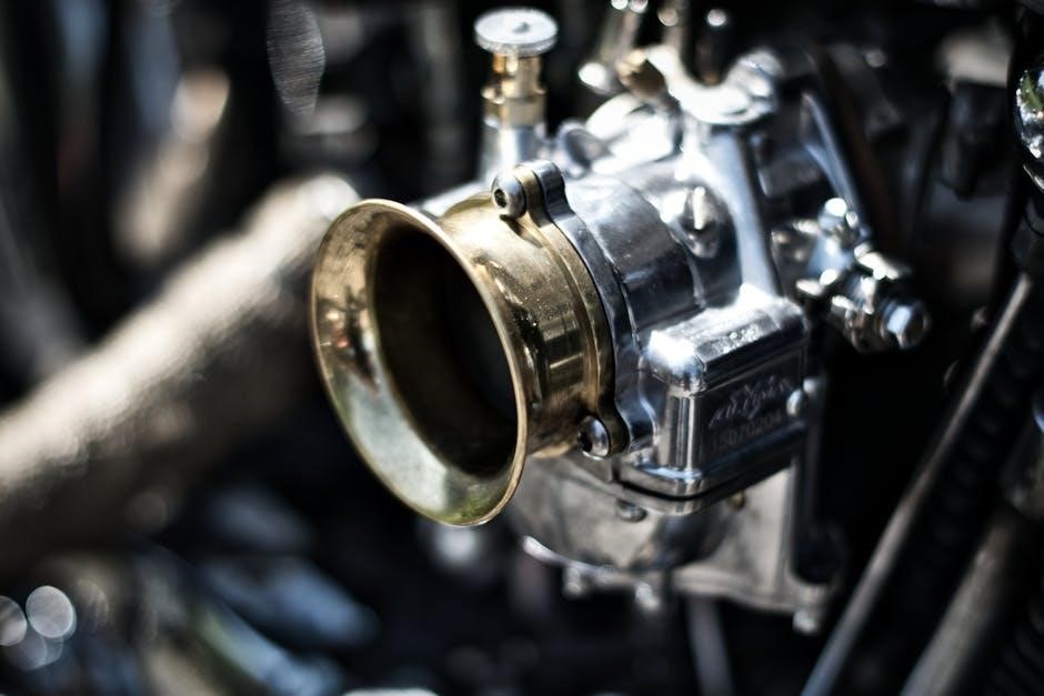
The Perkins 4-cylinder diesel engine features a advanced fuel system designed for optimal performance and efficiency. Utilizing a common rail fuel injection system, it ensures precise fuel delivery under various operating conditions. High-pressure fuel pumps and electronic control units work together to regulate fuel injection timing and quantity, minimizing emissions and maximizing power output. The system is equipped with fuel filters and water separators to maintain fuel purity and prevent contamination. This technology enhances combustion efficiency, reducing fuel consumption and lowering operational costs. Regular maintenance of the fuel system is essential to sustain its performance and reliability over time.

3.4 Emissions Standards and Compliance

Perkins 4-cylinder diesel engines are designed to meet stringent global emissions standards, ensuring environmental compliance and reduced emissions. These engines comply with EU Stage II, Stage III, and EPA Tier 2/Tier 3 regulations, making them suitable for various industrial and off-highway applications. Advanced emission control technologies, such as Diesel Oxidation Catalysts (DOC) and Diesel Particulate Filters (DPF), are integrated to minimize pollutants like NOx, PM, and CO. The engines also utilize Selective Catalytic Reduction (SCR) systems where required, ensuring adherence to emissions norms while maintaining fuel efficiency and performance. This commitment to environmental responsibility underscores Perkins’ dedication to sustainable engine technology.

Operation and Maintenance Guidelines

Proper operation and maintenance ensure optimal performance and longevity of the Perkins 4-cylinder diesel engine. Always follow the manufacturer’s guidelines for pre-start checks, routine servicing, and troubleshooting.

4.1 Pre-Operation Checks and Safety Precautions

Before starting the Perkins 4-cylinder diesel engine, ensure all pre-operation checks are completed. Check fuel and oil levels to avoid shortages during operation. Inspect the coolant level and ensure it’s within the recommended range. Look for any signs of leaks in fuel lines, hoses, or connections. Verify that all electrical connections are secure and free from damage. Wear appropriate safety gear, including gloves and safety glasses, to protect against potential hazards. Ensure the area is well-ventilated to prevent inhaling harmful fumes. Never start the engine with loose clothing or jewelry that could get caught in moving parts. Always refer to the manual for specific guidelines.

4.2 Routine Maintenance Schedule

A routine maintenance schedule is essential for optimal performance of the Perkins 4-cylinder diesel engine. Oil and filter changes should be performed every 50 hours or as specified in the manual. Inspect and replace air filters regularly to ensure proper airflow. Coolant levels should be checked monthly, and the system should be flushed every 2 years. Fuel filters must be replaced every 100 hours to prevent contamination. Inspect belts and hoses for wear and tear, and replace them as needed. Always follow the recommended maintenance intervals to prevent breakdowns and extend engine life.

4.3 Cooling System Maintenance

Regular cooling system maintenance is vital for preventing overheating and ensuring reliable operation of the Perkins 4-cylinder diesel engine. Inspect the radiator for dirt, debris, or leaks, and clean it as needed. Check coolant levels regularly and top up with a 50/50 mixture of water and antifreeze. Replace the coolant every 2 years or as specified in the manual. Inspect hoses and connections for signs of wear or damage. Additionally, ensure the water pump is functioning properly. Always use genuine Perkins parts for replacements to maintain system compatibility and performance. Follow the manual for specific maintenance intervals;

4.4 Lubrication and Oil Change Procedures

Proper lubrication is essential for the longevity and performance of the Perkins 4-cylinder diesel engine. Check the engine oil level daily using the dipstick, ensuring it remains within the recommended range. Use a high-quality diesel engine oil that meets Perkins specifications. Change the oil every 250-500 hours of operation, depending on usage conditions. Replace the oil filter with a genuine Perkins filter during each oil change. Drain the old oil responsibly and dispose of it in an environmentally friendly manner. Regular lubrication of moving parts, such as grease points, is also crucial for smooth operation. Always refer to the manual for specific intervals and guidelines.

Fuel System Overview and Maintenance

The Perkins 4-cylinder diesel engine’s fuel system ensures efficient combustion. Regular maintenance, including filter replacements and fuel line inspections, is crucial for optimal performance and reliability.

5.1 Components of the Fuel System

The Perkins 4-cylinder diesel engine’s fuel system comprises several critical components. These include the fuel tank, fuel lift pump, fuel filters, fuel injectors, and the fuel injection pump. The fuel tank stores the diesel fuel, while the lift pump creates suction to draw fuel from the tank. Fuel filters ensure clean fuel reaches the engine by removing contaminants. The fuel injectors spray fuel into the combustion chamber under high pressure, controlled by the injection pump. Proper functioning of these components is essential for efficient combustion and engine performance. Regular inspection and maintenance of these parts are vital to prevent fuel system malfunctions.

5.2 Fuel Injection System Operation

The fuel injection system in a Perkins 4-cylinder diesel engine operates by delivering fuel at high pressure into the combustion chamber at the correct timing. The fuel injection pump, driven by the engine, pressurizes the fuel and meters it according to engine speed and load. The electronic control unit (ECU) regulates injection timing and fuel quantity for optimal performance. Fuel is sprayed through injectors into the cylinders, ensuring efficient combustion. This precise process maximizes power output, reduces emissions, and improves fuel efficiency. Proper synchronization of these components is critical for smooth engine operation and overall performance.

5.3 Troubleshooting Fuel System Issues

Common fuel system issues in Perkins 4-cylinder diesel engines include air in the system, clogged fuel filters, and faulty injectors. Symptoms like hard starting, rough running, or loss of power often indicate a problem. To diagnose, check the fuel filter for blockages and replace it if necessary. Bleed the system to remove air, ensuring proper fuel flow. Inspect fuel lines for leaks or damage and test injector performance. Low fuel pressure or faulty pressure regulators can also cause issues. Addressing these problems promptly prevents engine damage and ensures reliable operation. Always consult the manual for specific troubleshooting procedures.

5.4 Maintenance Tips for Optimal Fuel Efficiency

To maximize fuel efficiency in your Perkins 4-cylinder diesel engine, regular maintenance is essential. Ensure air, fuel, and oil filters are clean or replaced as recommended. Check fuel lines for leaks or damage and address them promptly. Maintain proper injector performance by cleaning or replacing them as needed. Keep the cooling system in good condition to prevent overheating, which can reduce efficiency. Regularly inspect and service the fuel pump and pressure regulator. Always use the correct grade of diesel fuel specified in the manual. Proper engine tuning and timely servicing can significantly enhance fuel economy and overall performance.

Electrical System and Components

The Perkins 4-cylinder diesel engine features a robust electrical system, including a high-capacity battery, alternator, and wiring harness. Essential components like the starter motor and circuits ensure reliable engine operation.

6.1 Overview of the Electrical System

The Perkins 4-cylinder diesel engine’s electrical system is designed for reliability and efficiency. It includes a heavy-duty battery, high-output alternator, and a durable wiring harness. The system powers essential components like the starter motor, fuel injection system, and engine control unit. Advanced circuit protection ensures safety and prevents damage from overloads or short circuits. The electrical system is integrated with other engine systems, such as fuel injection and diagnostics, to optimize performance and monitoring. Regular maintenance, as outlined in the manual, ensures consistent operation and prevents electrical failures. This robust system supports both on-road and off-road applications.

6.2 Battery and Charging System

The Perkins 4-cylinder diesel engine’s battery and charging system are crucial for reliable starting and electrical power. Heavy-duty batteries are recommended to handle the engine’s high compression requirements. The charging system features a high-output alternator designed to efficiently recharge the battery and support electrical loads while the engine operates. Proper maintenance involves regular checks of battery terminals, ensuring correct charging voltages, and avoiding deep discharges. Always use genuine or compatible parts to maintain system reliability and performance. Regular inspections and adherence to the manual’s guidelines ensure consistent operation, prevent electrical failures, and extend the system’s lifespan.

6.3 Alternator and Voltage Regulation

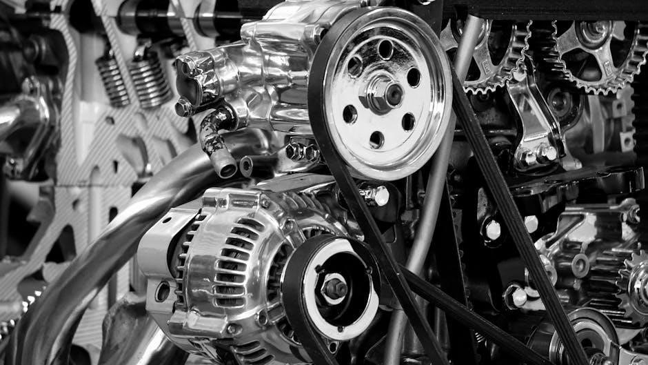
The Perkins 4-cylinder diesel engine features a robust alternator and voltage regulation system to ensure stable electrical power supply. The alternator is designed to charge the battery and power electrical systems efficiently, even under heavy loads. A built-in voltage regulator maintains consistent output, typically between 13.5V to 14.5V, to prevent overcharging and protect electrical components. Regular inspection of the alternator belt and connections is essential for optimal performance. Proper alignment and tension of the belt ensure reliable operation, while periodic testing of voltage output helps identify potential issues early. This system is critical for maintaining engine reliability and electrical system health.

6.4 Electrical System Diagnostics

Diagnosing electrical system issues in the Perkins 4-cylinder diesel engine requires a systematic approach. Start by checking the battery voltage using a multimeter to ensure it is within the recommended range. Inspect all wiring and connections for signs of wear or corrosion. Use the engine’s diagnostic scanner to identify fault codes, which can pinpoint issues like faulty sensors or relays. Test the alternator output to confirm it is charging correctly. Refer to the manual for specific troubleshooting procedures and wiring diagrams. Regular diagnostics help prevent electrical failures and ensure reliable engine operation. Always follow safety guidelines when working with electrical systems.

Cooling System Function and Maintenance

The cooling system ensures optimal engine temperature regulation, preventing overheating. It includes radiators, hoses, and a water pump. Regular coolant checks and flushes are essential.

7.1 Importance of the Cooling System

The cooling system is vital for maintaining optimal engine temperature, preventing overheating, and ensuring reliable operation. It protects engine components from thermal damage, enhancing longevity. Proper cooling also improves fuel efficiency and reduces emissions. A well-functioning system prevents premature wear on cylinders, pistons, and valves. Regular maintenance ensures consistent performance, especially in demanding environments. Neglecting the cooling system can lead to engine failure, costly repairs, and downtime. Thus, prioritizing its upkeep is crucial for sustaining the Perkins 4-cylinder diesel engine’s productivity and overall health.

7.2 Components of the Cooling System

The cooling system of the Perkins 4-cylinder diesel engine includes several critical components designed to manage heat effectively. The radiator is central, dissipating heat from the coolant. The water pump circulates coolant through the engine block and cylinder head. Hoses connect these components, ensuring coolant flow. The thermostat regulates engine temperature by controlling coolant circulation. Additionally, the cooling fan enhances heat dissipation, especially at low speeds. Together, these components ensure optimal engine temperature, preventing overheating and maintaining performance. Regular inspection and maintenance of these parts are essential for reliable engine operation.

7.3 Maintenance and Troubleshooting Tips

Regular maintenance of the cooling system is crucial for optimal performance. Check coolant levels daily and top up as needed using a 50/50 water-antifreeze mix. Inspect hoses for cracks or leaks and replace them if necessary. Clean the radiator fins and fan regularly to ensure proper airflow. If overheating occurs, check for blockages in the radiator or hoses. Bleed the system to remove airlocks, which can cause inefficient cooling. Replace the thermostat if it fails to open or close properly. Always refer to the Perkins manual for specific guidelines and troubleshooting steps to maintain engine health and prevent damage.

7.4 Upgrading the Cooling System

Upgrading the cooling system can enhance engine performance and durability. Consider installing a high-performance radiator with improved heat dissipation. Upgraded coolant hoses with reinforced materials can withstand higher pressures and temperatures. A high-capacity water pump ensures consistent coolant circulation. Additionally, aftermarket cooling fans with better airflow can improve efficiency. When upgrading, ensure all components are compatible with your Perkins engine. Always follow the manual’s guidelines for installation and compatibility. Professional installation is recommended to avoid system malfunctions. Regularly review the manual for upgrade options tailored to your engine model and operational demands.

Troubleshooting Common Issues

Troubleshooting common issues in your Perkins 4-cylinder diesel engine involves identifying problems early, using diagnostic tools, and consulting the manual for repair guidance. Act promptly to prevent damage.

8.1 Identifying and Diagnosing Common Problems

Identifying and diagnosing common problems in a Perkins 4-cylinder diesel engine begins with recognizing symptoms like unusual noises, warning lights, or reduced performance. Always refer to the manual for specific guidance. Use diagnostic tools to pinpoint issues such as fault codes or sensor malfunctions. Regularly inspect fuel, oil, and coolant levels, as low levels often trigger problems. Look for signs of wear or leaks in key components like fuel injectors or hoses. Early detection prevents minor issues from escalating into major repairs. Consult the manual’s troubleshooting section for step-by-step solutions tailored to your engine model.

8.2 Solutions for Engine Overheating

Addressing engine overheating in a Perkins 4-cylinder diesel engine involves identifying the root cause. Start by checking coolant levels and ensuring proper coolant circulation. Inspect the radiator for blockages or damage and clean or replace it if necessary. Verify that the water pump is functioning correctly and replace it if faulty. Check the thermostat for proper operation and ensure the cooling fan is working as intended. Avoid overheating by maintaining the recommended coolant-to-water ratio and ensuring good airflow around the engine compartment. Refer to the manual for specific procedures to resolve overheating issues effectively and prevent engine damage.

8.3 Addressing Low Power Output Issues

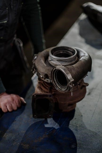
Low power output in a Perkins 4-cylinder diesel engine can result from various factors. Check the fuel system for dirty or clogged fuel filters and ensure proper fuel flow. Inspect the air filter for cleanliness and replace it if necessary to maintain adequate airflow. Verify the condition of the turbocharger, as damage or blockages can significantly reduce power. Additionally, check the exhaust system for restrictions or leaks. Regular servicing, including compression tests and injection system checks, can help identify and resolve issues. Always consult the manual for specific diagnostic procedures and adjustments to restore optimal performance.

8.4 Resolving Fuel System Malfunctions

Resolving fuel system malfunctions in a Perkins 4-cylinder diesel engine involves identifying and addressing issues promptly. Common problems include fuel contamination, clogged fuel filters, or faulty fuel injectors. Begin by inspecting the fuel tank for dirt or water and draining it if necessary. Replace the fuel filters and check the fuel lines for blockages or leaks. Ensure the fuel injection system is clean and functioning properly, as dirty or worn injectors can disrupt fuel flow. Additionally, check the fuel pump for low pressure or failure. Regular maintenance, such as filter replacements and system bleeding, can prevent malfunctions and ensure reliable engine performance.

Parts and Accessories for Perkins 4 Cylinder Engines

Explore a wide range of genuine and aftermarket parts, essential tools, and accessories designed to maintain, repair, and enhance the performance of Perkins 4-cylinder engines.

9.1 Genuine vs. Aftermarket Parts

When maintaining or repairing a Perkins 4-cylinder diesel engine, choosing between genuine and aftermarket parts is crucial. Genuine parts are manufactured by Perkins, ensuring precise fitment, reliability, and compliance with original specifications. They often come with warranties and are recommended for maintaining engine performance and longevity. Aftermarket parts, while cost-effective, may vary in quality and compatibility. They can be a budget-friendly option but may lack the same level of testing and certification as genuine components. Always verify the manufacturer’s reputation and specifications to ensure optimal performance and durability for your engine.

9.2 Essential Tools for Maintenance and Repair

Maintaining and repairing a Perkins 4-cylinder diesel engine requires a set of essential tools to ensure efficiency and safety. Basic tools include wrenches, screwdrivers, pliers, and sockets. Specialized tools like a torque wrench, compression tester, and fuel injection testers are also necessary for specific tasks. Diagnostic tools, such as multimeters and scan tools, help identify issues. Always use high-quality tools that meet the specifications outlined in the manual. Proper tools prevent damage to engine components and ensure accurate repairs, adhering to safety and performance standards. Regularly inspect and maintain tools to keep them in good working condition.

9.3 Where to Source Reliable Parts

Reliable parts for the Perkins 4-cylinder diesel engine can be sourced from authorized Perkins dealers, ensuring genuine components. Independent suppliers and online retailers may also offer high-quality alternatives. Always verify the authenticity of parts by checking for Perkins branding, serial numbers, or certifications. Purchasing from reputable sources guarantees compatibility and performance. Additionally, consider contacting engine rebuild specialists or local distributors for hard-to-find components. Warranties and return policies are essential safeguards when buying parts. Prioritize suppliers with good customer reviews and technical support to ensure long-term engine reliability and performance.

9.4 Accessories to Enhance Performance

To optimize your Perkins 4-cylinder diesel engine, consider high-performance accessories like upgraded air filters for improved airflow and fuel efficiency. Performance exhaust systems can reduce backpressure, enhancing power output. Electronic control unit (ECU) tuning kits are another option, allowing precise calibration for increased torque and horsepower. Additionally, aftermarket turbochargers or intercoolers can boost performance under heavy loads. Always consult the manual or a certified technician to ensure compatibility and avoid voiding warranties. These accessories can significantly enhance engine performance and reliability, especially in demanding industrial or agricultural applications.

how to install valve guides

Valve guides are critical for engine performance, ensuring proper valve alignment and reducing wear. Their installation requires precision, involving removal of old guides, precise measurement, and careful seating to maintain engine integrity and efficiency.

Overview of Valve Guides and Their Importance

Valve guides are critical components in an engine’s cylinder head, serving as the pathway for valves to open and close properly. They ensure precise alignment, preventing sideways motion that could damage the valve or cylinder head. Guides also play a key role in sealing engine oil, preventing it from entering the combustion chamber. Over time, valve guides can wear out, leading to increased oil consumption, reduced performance, and potential engine damage. Proper installation and maintenance of valve guides are essential for maintaining engine efficiency, preventing costly repairs, and ensuring optimal combustion chamber sealing. Their condition directly impacts engine longevity and overall performance.

Why Valve Guide Installation Is Necessary

Installing valve guides is essential for maintaining proper engine operation and preventing potential damage. Worn-out guides can lead to misaligned valves, causing inefficient combustion and reduced engine performance. They prevent oil leakage into the combustion chamber, which can result in increased oil consumption and emissions. Properly installed guides ensure valves close tightly, maintaining compression and preventing overheating. They also protect against valve damage from misalignment, which can lead to costly repairs. Regular installation of new guides is a proactive step to uphold engine efficiency, prevent breakdowns, and ensure smooth overall engine function. This maintenance is crucial for extending the lifespan of your engine and avoiding more severe issues down the line.

Preparation for Valve Guide Installation

Preparation involves gathering tools, cleaning the workspace, and ensuring safety measures are in place for a smooth process and to avoid potential risks or errors.

Tools and Materials Required

To install valve guides, you’ll need specialized tools like a valve guide installer, reamer, and puller. Essential materials include new valve guides, lubricant, and sealant. Ensure you have a torque wrench, screwdrivers, and protective gear for safety. A well-lit workspace with a stable workbench is also crucial for precision and safety during the process.

Safety Precautions and Workspace Setup

When preparing for valve guide installation, prioritize safety by wearing gloves, safety glasses, and a face mask. Ensure your workspace is well-ventilated, clean, and illuminated to minimize risks. Use a sturdy workbench and secure the cylinder head firmly to prevent movement. Keep power tools and flammable materials apart, and maintain an organized, clutter-free area. Avoid loose clothing and tie back long hair to prevent entanglements with tools. Have a fire extinguisher and first aid kit readily available. Proper workspace setup and adherence to safety guidelines are essential for a smooth and safe installation process.

Removing the Old Valve Guides

Access the cylinder head and use specialized tools like a slide hammer or extractors for safe removal. Apply heat or freezing to aid in loosening stuck guides. Proceed with caution to avoid damage, especially if guides are broken or seized. Consider professional assistance if unsure.

Methods for Removing Valve Guides

Several methods exist for removing old valve guides, each requiring care to avoid damaging the cylinder head. The slide hammer method involves attaching the tool to the guide and using a pulling motion. Thermal shocking uses heat to expand the guide, easing removal. For stubborn guides, freezing the area can help loosen them. In some cases, a drill press may be used to create pilot holes for extraction tools. Combining methods is often necessary, especially for stuck or broken guides. Regardless of the technique, precision is key to prevent cylinder head damage. If unsure, consulting a professional is advisable to ensure a successful removal process.

Using Freezing to Ease Removal

Freezing the valve guide area can significantly simplify the removal process. By applying dry ice or liquid nitrogen, the metal contracts, reducing the bond between the guide and the cylinder head. This method is particularly effective for stuck or corroded guides. Safety is paramount; wear gloves and goggles when handling frozen materials. Allow the area to cool for 15–20 minutes. Once contracted, use a slide hammer or extraction tool to remove the guide. Be cautious not to apply heat immediately after freezing, as this could cause sudden expansion. Freezing is a non-destructive approach, minimizing the risk of damage to the surrounding material. Proper timing and technique ensure a smooth removal process.

Extracting Without Special Tools

Extracting valve guides without special tools requires careful planning and caution. One effective method is to use a slide hammer, which can generate significant force to pull out the guide. Alternatively, basic tools like wrenches or pliers can be employed, though they may not provide enough force. Applying heat with a hairdryer or heat gun can help expand the metal around the guide, making removal easier, but be cautious not to overheat the cylinder head. Penetrating oil can also be used to loosen corrosion or grime; Safety is paramount; wear gloves and safety glasses to protect against flying debris. If the guide is severely stuck, it may be necessary to seek professional assistance to avoid damaging the cylinder head.

Dealing with Broken or Stuck Valve Guides

When encountering broken or stuck valve guides, proceed with caution to avoid further damage. If the guide breaks during removal, use a drill to create a pilot hole in the remaining fragment. Then, employ an extraction tool or slide hammer to carefully pull out the pieces. For stuck guides, apply penetrating oil to loosen corrosion and let it sit overnight. Heat can also be applied to expand the metal, aiding removal. If the guide is severely stuck, avoid forcing it, as this may damage the cylinder head. In challenging cases, seeking professional assistance is recommended to prevent costly repairs. Safety glasses and gloves should always be worn to protect against debris.

Inspecting and Measuring the Cylinder Head

Inspect the cylinder head for cracks, wear, or damage. Use a micrometer to measure guide bore dimensions and ensure proper alignment. Check surface flatness and cleanliness. Wear gloves and safety glasses for protection.

How to Measure Valve Guide Clearance

To measure valve guide clearance, start by using a dial bore gauge to measure the guide bore’s inner diameter. Compare this measurement to the manufacturer’s specifications. Next, measure the valve stem’s outer diameter using a micrometer. The difference between these two measurements gives the clearance. Ensure the gauge is calibrated and properly seated within the bore for accurate readings. Excessive clearance may indicate wear, requiring reaming or replacement. Always follow the vehicle manufacturer’s guidelines for acceptable clearance tolerances. Proper measurement is critical to ensure correct valve guide installation and optimal engine performance. Wear protective gloves and eyewear during this process for safety.

Assessing Cylinder Head Condition

Before installing new valve guides, inspect the cylinder head for cracks, excessive wear, or damage. Use a straightedge and feeler gauge to check the head’s flatness, ensuring it meets manufacturer specifications. Inspect the valve seats for pitting, burn marks, or uneven wear, as these issues may require machining. Look for signs of head gasket leakage or corrosion, which could compromise the installation. Use a magnaflux test to detect cracks in critical areas. Check the head bolt threads for damage or stripping. If any defects are found, the cylinder head may need reconditioning or replacement before proceeding with valve guide installation. A damaged head can lead to poor engine performance or leaks, even with new guides installed.

Reaming and Preparing the Valve Guide Area

Use a reamer to enlarge worn valve guide holes, ensuring proper fit for new guides. Clean and inspect the area thoroughly before installation to ensure accuracy.

Reaming Techniques for Worn Guides

Reaming is essential for restoring worn valve guide holes to the correct diameter. Start by using a pilot reamer to create a precise guide for the final reamer. Gradually increase the reamer size until the hole reaches the specified dimension. Always maintain proper alignment to avoid misshapen holes. Use cutting oil to lubricate the reamer and prevent overheating. After reaming, inspect the area for any debris or burrs. If the guides are severely worn, consider oversizing them. Finally, clean the area thoroughly with compressed air and solvent to ensure a smooth installation process. Proper reaming ensures a snug, accurate fit for the new valve guides, crucial for optimal engine performance.

Preparing the Area for New Guides

After reaming, the area must be meticulously prepared for the new valve guides. Start by cleaning the cylinder head surface and guide holes using a solvent and compressed air to remove debris. Inspect for any remaining old adhesive or residue and scrape it off carefully. Lightly sand the surrounding area to ensure a smooth, even surface for the new guides. Apply a thin, even layer of high-temperature adhesive to the back of the new guide, following the manufacturer’s instructions. Use an alignment tool to ensure the guide is properly positioned before pressing it into place. Allow the adhesive to set as directed to ensure a secure bond. Proper preparation guarantees a precise fit and prevents future issues. This step is critical for the longevity and performance of the valve guides. Always double-check alignment before final placement.

Installing the New Valve Guides

Ensure the new guides are properly aligned and seated. Use specialized tools to press them into place gently but firmly. Verify correct fitment and alignment before finalizing the installation. Always refer to the manufacturer’s specifications for torque and seating depth. Proper installation ensures optimal engine performance and longevity of the guides. Double-check the valve train operation after installation to confirm everything functions smoothly.

Cleaning and Lubricating the Area

Cleaning the valve guide area is essential before installation to ensure proper fitment and prevent contamination. Use a solvent to remove old lubricants, grime, and debris from the cylinder head and guide bore. Dry the area thoroughly with compressed air to eliminate moisture. Lightly lubricate the new valve guide with motor oil or a specialized lubricant to reduce friction during installation. Apply a thin layer of lubricant to the valve stem as well to ensure smooth operation. Avoid over-lubricating, as excess can attract dirt and cause premature wear. Proper cleaning and lubrication are critical for optimal performance and longevity of the valve train components.

Aligning the New Valve Guides

Aligning the new valve guides is a critical step to ensure proper seating and function. Start by using a dial indicator to verify the guide bore is centered relative to the valve seat. Next, carefully position the new guide into the bore, ensuring it aligns with the valve stem and seat. Use a guide pilot or alignment tool to maintain proper orientation. Gently tap the guide into place using a soft-faced hammer, checking alignment frequently. Avoid forcing the guide, as this could cause misalignment or damage. Once seated, verify the guide is flush with the cylinder head surface and evenly spaced around the bore. Proper alignment prevents engine performance issues and extends the lifespan of the valve train components.

Heat Application for Proper Seating

Heat application is essential for ensuring the new valve guides seat properly. Use a heat gun to warm the cylinder head around the guide bore to approximately 200–300°F. This allows the metal to expand slightly, making it easier to press the guide into place. Apply heat evenly around the bore to avoid uneven expansion. Once heated, carefully press the guide into the bore using a suitable installation tool. Ensure the guide is fully seated and aligned before allowing the head to cool. This process ensures a tight, even fit, preventing future leaks or misalignment. Avoid overheating, as this can damage the cylinder head or guide. Always use thermal protective gear when handling heated components.

Testing and Inspection Post-Installation

After installation, inspect the valve guides for leaks and ensure they are properly seated. Check the valve train operation and alignment to confirm everything functions smoothly.

Checking for Leaks and Proper Seating

After installing the new valve guides, perform a thorough leak test to ensure there are no gaps or improper seals. Use compressed air to pressurize the cylinder head and listen for hissing sounds, which indicate leaks. Visually inspect the valve guide area for any signs of misalignment or improper seating. Check the valve train operation to confirm that the valves move smoothly without binding or excessive play. Ensure the guides are securely seated and aligned with the valve stems. If any issues are detected, reseat the guides or replace the seals as needed. Proper seating and sealing are critical for optimal engine performance and longevity.

Final Inspection and Adjustments

Once the valve guides are installed and tested, conduct a final inspection to ensure everything is in proper order. Verify that all guides are evenly seated and aligned with the valve stems. Check the valve train for smooth operation, ensuring no binding or excessive clearance. Inspect the area for any residual debris or lubricant residue. Apply a small amount of lubricant to the valve stems and guides to facilitate smooth operation. Start the engine and listen for any unusual noises or vibrations, which could indicate improper installation. Address any issues promptly to prevent further damage. This step ensures the repair is reliable and maintains engine performance.

Maintenance and Upkeep

Regular maintenance ensures valve guides remain functional. Inspect for wear, clean debris, and lubricate moving parts. Monitor engine performance and address issues promptly. Schedule routine checks.

Regular Maintenance to Prevent Wear

Regular maintenance is crucial to extend the life of valve guides. Inspect valve guide clearance periodically using a feeler gauge to ensure proper alignment and fitment. Clean the area around the guides to prevent debris buildup, which can cause wear. Lubricate the valve stem and guide with engine oil or silicone-based grease to reduce friction. Check for signs of wear, such as excessive oil consumption or valve train noise. Addressing these issues early prevents further damage. Additionally, ensure the cylinder head is free from cracks or corrosion, as this can affect guide stability. Regular maintenance not only prevents wear but also ensures optimal engine performance and longevity. Always follow the manufacturer’s recommendations for inspection intervals. Consistent upkeep helps maintain proper valve train operation and prevents costly repairs down the line.

When to Replace Valve Guides Again

Determine the need for replacing valve guides by monitoring engine performance and signs of wear. Increased oil consumption, excessive smoke, and engine noise are key indicators of worn guides. If the valve train exhibits significant wear or clearance issues, replacement is essential to maintain proper engine function. Replacing them prevents further damage and ensures optimal performance. Always adhere to proper installation procedures to maximize their lifespan. Regular inspections and timely interventions can significantly enhance engine efficiency and longevity, avoiding costly repairs.

Common Mistakes and Troubleshooting

Common errors include improper alignment, insufficient lubrication, and using incorrect tools. These mistakes can lead to uneven seating or damage to the cylinder head. Always verify guide alignment and ensure proper lubrication before installation. Addressing these issues promptly prevents costly repairs and ensures long-term performance.

Avoiding Common Errors During Installation

During valve guide installation, common errors include improper alignment, insufficient lubrication, and using incorrect tools. Misalignment can lead to uneven wear and poor engine performance. Inadequate lubrication may cause friction and premature damage to the new guides. Using the wrong tools can result in improper seating or damage to the surrounding area. To avoid these issues, ensure precise alignment, apply the recommended lubricant, and use specialized tools designed for valve guide installation. Double-checking measurements and following manufacturer guidelines can significantly reduce the risk of errors. Proper technique and attention to detail are crucial for a successful installation and optimal engine function.

Troubleshooting Post-Installation Issues

After installing valve guides, common issues include leaks, improper seating, or heat-related problems. If leaks occur around the valve guides, inspect the area for proper sealing and ensure the guides are tightly seated. Apply a smoke test or vacuum gauge to identify leak sources. If the issue persists, re-torque the guide or replace it if damaged. Improper seating may cause valve train noise or performance loss; check for debris or misalignment. Heat issues can arise if guides are not seated correctly, leading to premature wear. Address these by ensuring proper installation and alignment. Always refer to the repair manual for specific troubleshooting steps tailored to your engine type.

Installing valve guides requires precision and care. Proper techniques ensure optimal engine performance and longevity. Regular maintenance is crucial for preventing future issues and ensuring reliability.

Installing valve guides involves thorough preparation, precise removal of old guides, and careful installation of new ones. Proper tools and safety measures are essential to avoid damage. Inspecting the cylinder head and reaming the area ensures a smooth fit. Aligning and heating the new guides guarantees proper seating. Post-installation testing is critical to confirm leaks are sealed and performance is optimized. Regular maintenance helps prevent future wear. Following manufacturer guidelines and avoiding common mistakes ensures longevity. Precision and patience are key to a successful installation, as improper techniques can lead to engine issues. Always prioritize quality materials and proper fitting for reliable engine operation.